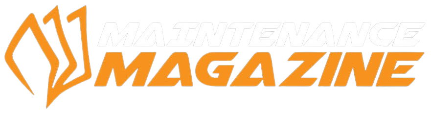
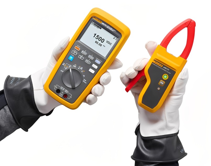
Fluke 283FC PV EUR LCD Multimeter
Working on solar photovoltaic arrays demands precision, confidence, and disciplined safety habits. Fluke 283FC PV EUR LCD Multimeter is built for professionals who troubleshoot high voltage DC environments where every measurement must be clear, stable, and dependable.
Because PV systems combine strong sunlight, long cable runs, and sensitive electronics, you need a multimeter that supports accurate diagnostics without slowing your workflow. With the right approach, you can verify performance, reduce downtime, and protect people and equipment across installations.
Why PV testing needs a purpose-built multimeter
Solar PV circuits behave differently from typical building power. Although AC systems dominate many sites, PV strings deliver DC power that can remain energized whenever light hits the panels. As a result, you must treat testing as an energized task from the first probe contact to the final verification step.
At the same time, modern PV sites include controllers, inverters, and monitoring hardware connected through connectors and long cable routes. Therefore, you need consistent readings that help you pinpoint issues quickly, especially during commissioning and maintenance.
Common PV measurement challenges
PV work often includes conditions that can distort readings or hide faults. For example, heat, vibration, and tight enclosures can push tools beyond their comfort zone. In addition, mixed loads and switching behavior from electronics can create confusing symptoms.
Typical challenges include:
- Voltage drop across long cables and connections
- Loose connectors causing intermittent behavior
- Damaged insulation near contactors, fuses, and switches
- Temperature effects on performance and stability
- Sensitive electronics near microcontrollers and controllers
What makes Fluke 283FC PV EUR LCD Multimeter relevant on site
Fluke 283FC PV EUR LCD Multimeter supports the kind of structured testing PV technicians rely on. Instead of guessing, you can validate the system step by step and document what you observe so the next visit starts with facts.
It also fits real work environments where you may wear gloves, handle tools with firm grips, and move between rooftop arrays and plant rooms. When time matters, you want quick access to stable readings and a display that remains easy to interpret.
Clear measurement workflow for PV strings
A reliable multimeter helps you move from safe setup to confident conclusions. You can verify DC voltage levels, check continuity where appropriate, and compare results across strings to locate abnormal behavior.
A practical PV routine often includes:
- Confirm system state and isolation points before probing
- Verify DC voltage at key test points, then compare across strings
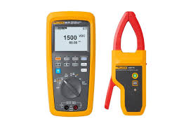
- Inspect connectors and cables for damage, heat marks, or looseness
- Check protective devices such as fuses and switches for integrity
- Re-test after corrective actions to confirm improvement
Because PV faults can hide in small resistive losses, repeating tests after cleaning or tightening connections often reveals the true cause.
Using the right accessories and habits for safer diagnostics
Even the best multimeter depends on disciplined technique. Before you start, inspect your leads and accessories as carefully as the circuit you plan to test. Worn insulation, loose probe tips, or incorrect rating choices increase risk and create unreliable results.
Choose quality test cables and keep them organized. Also, avoid placing leads near sharp edges or hot surfaces where thermal stress can weaken insulation over time.
Practical safety habits that reduce risk
Safety improves when you standardize how you measure. Moreover, consistent habits reduce errors during busy site work and make your results more comparable.
Use habits like these:
- Select the correct function and range before making contact
- Keep hands behind finger guards and maintain stable grips
- Use one hand where possible and keep posture balanced
- Re-check readings after moving probes to confirm stability
- Stop and reassess if values look abnormal or inconsistent
Additionally, keep a clean work area. Loose hardware, oils, and dust can degrade insulation and interfere with connectors, especially in outdoor enclosures.
Diagnosing heat-related issues with thermal awareness
Temperature affects PV performance and can expose weak connections. Although the multimeter measures electrical values, you can use thermal awareness to decide where to test next. For example, a warm connector or terminal often correlates with high resistance and voltage drop.
When technicians pair electrical readings with temperature checks, they often find faults faster. This approach also supports better preventive maintenance, since early detection prevents failures later.
Where heat commonly appears
Heat typically builds up where current meets resistance. Therefore, focus on junction points and protection components.
Common hot spots include:
- Connectors that loosen under vibration
- Contactors and terminals with incomplete tightening
- Fuses and holders with worn contact surfaces
- Switches that arc or age under repeated use
- Cable lugs affected by corrosion or improper crimping
Also, remember that thermal pads and heat transfer materials can influence enclosure temperature management. Poor installation or aging pads may contribute to higher internal temperatures and faster component wear.
Supporting electronics and controls in PV systems
PV installations increasingly integrate smart monitoring and control. You may test around electronics such as data loggers, sensor interfaces, and protective relays. In these areas, stable readings help you confirm power quality and identify issues that cause resets or communication failures.
You might also work near microprocessors, microcontrollers, and power management stages where small voltage changes matter. Therefore, careful probing and consistent measurement practice become essential, especially when validating low-voltage rails feeding controllers.
Checking sensors and signal paths effectively
Many PV sites depend on sensors for monitoring temperature, irradiance, or current flow. When a sensor chain fails, the system may throttle output or trigger alarms. A strong troubleshooting method compares expected values with actual readings at the sensor, the cable run, and the input point.
To stay organized, you can:
- Verify supply voltage at the sensor and at the controller input
- Inspect connectors for pin damage or moisture intrusion
- Check continuity through cables after isolating circuits
- Compare readings across similar sensors to detect outliers
This method reduces guesswork and supports faster restoration.
Keeping documentation simple and useful
Professional maintenance improves when you capture consistent data. Even basic logs help you track how a system changes seasonally and how repairs affect performance. If you service multiple sites, documentation also saves time and helps other technicians understand what you verified.
Write down key readings, environmental conditions, and any changes you made. In addition, note whether issues appeared during peak sun, partial shade, or early morning conditions, since PV behavior shifts with light and temperature.
Why this multimeter fits modern PV service work
Fluke 283FC PV EUR LCD Multimeter aligns with the practical needs of PV technicians who work in high voltage DC environments. It supports structured troubleshooting, encourages safer habits, and helps you confirm results clearly in the field.
When you combine a disciplined testing routine, quality cables and connectors, and awareness of thermal behavior, you can diagnose faults faster and maintain consistent performance. Ultimately, strong measurement practices protect equipment, improve uptime, and keep safety at the center of every PV job.