
Fluke Voltage Indicator: What Makes It Essential for Safe Testing?
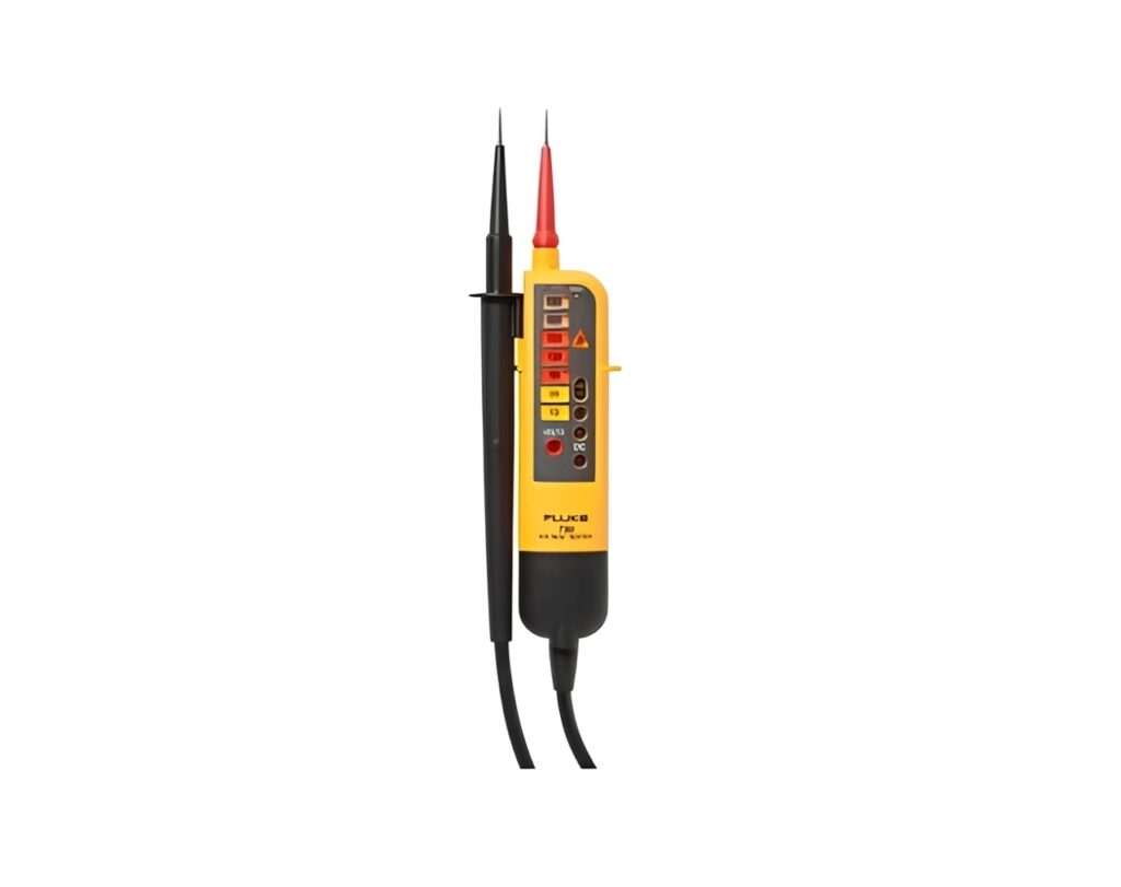
A Fluke Voltage Indicator is a practical tool for quickly confirming whether a circuit is live before you touch conductors, terminals, or equipment. Because electrical work often begins with a simple question, is it energized, a dependable voltage indicator helps you reduce risk while keeping troubleshooting efficient. In addition, when you follow the right test routine, you gain confidence that your readings reflect real conditions, not guesswork.
Why a Fluke Voltage Indicator matters in electrical safety
Electrical safety improves when verification becomes a habit, not a last step. A voltage indicator supports this habit by giving fast feedback at the point of work.
Key reasons professionals rely on a voltage indicator include:
- Confirming presence or absence of voltage before handling cables, connectors, or contactors
- Reducing the chance of accidental contact with energized parts
- Speeding up fault isolation when a system will not start
- Supporting lockout tagout routines by validating isolation points
Moreover, the best approach pairs the tool with disciplined procedure. You should always treat circuits as live until proven otherwise.
How a Fluke Voltage Indicator works with real circuits
Most voltage indicators detect voltage by making contact with test points, and some models also provide non contact detection for quick screening. The indicator then communicates status using LEDs, audible alerts, or a display, depending on the model.
However, real installations include noise, induced voltages, long cable runs, and switching devices. Therefore, you should interpret results with context:
- Long parallel cables can pick up induced voltage even when disconnected
- Electronic loads and controllers can store charge in a capacitor bank briefly
- LEDs in modern devices can glow faintly due to leakage paths
- Thermal stress and aged insulation can change behavior over time
Because of these variables, a correct testing sequence is as important as the tool itself.
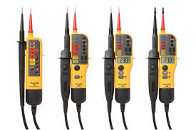
Choosing the right Fluke Voltage Indicator for your application
Different jobs demand different features. A field technician checking distribution panels will prioritize speed and visibility, while a controls engineer may want clearer indication around contactors and control circuits.
Consider the voltage range and environment
Match the tool to your typical work:
- Low voltage control circuits for PLCs and microcontrollers
- Mains distribution, single phase or three phase systems
- Mixed electronics cabinets containing sensors, controllers, and switching devices
Also consider environmental demands:
- Crowded panels where probe grips and lead flexibility matter
- Dusty sites where sealed construction helps
- Poor lighting where bright LEDs improve visibility
Look for usability features that improve accuracy
Small design choices can reduce mistakes:
- Clear polarity or level indication so you interpret results quickly
- Strong grips and stable probe tips for secure contact
- Simple alert patterns that are easy to recognize under pressure
- Durable cables and strain relief to reduce intermittent connections
In addition, if you frequently work near rotating equipment or moving machinery, probe control and cable routing become even more important.
Safe testing workflow: a practical step by step routine
A reliable routine helps you avoid false readings. Use this sequence whenever possible.
Step 1: Inspect before you test
Start with a quick visual and physical check:
- Confirm probes, cables, and connectors are intact
- Look for cracked insulation or loose strain relief
- Ensure the tool is clean and dry, especially if oils are present
- Verify the probe tips are not worn or bent
If any component looks damaged, replace it before testing.
Step 2: Prove the indicator on a known live source
Before testing the target circuit, confirm the tool responds correctly:
- Touch a known live outlet or test point
- Confirm the LEDs or alert signals match expectation
This step prevents time wasted on a dead battery or a failed lead.
Step 3: Test the target points with steady contact
Now check the circuit you plan to work on:
- Contact the correct terminals, not adjacent hardware
- Use firm, stable pressure and keep your hands behind finger guards
- Watch for consistent indication, not a brief flicker
If you are checking a panel with multiple contactors, test the supply side and load side to confirm isolation.
Step 4: Re prove the indicator after the test
Finally, re test the known live source again:
- Confirm the indicator still responds normally
This bookend method helps validate that the tool worked throughout the process.
Common use cases where this product shines
A Fluke Voltage Indicator is especially useful when you need quick confirmation without slowing down the job.
Typical scenarios include:
- Verifying a circuit is de energized before replacing switches or fuses
- Checking presence of voltage at connectors on equipment and machines
- Confirming power delivery to control cabinets with controllers and sensors
- Troubleshooting intermittent faults in cables and terminal blocks
- Identifying whether a contactor is actually receiving supply voltage
Additionally, in installations with laptops and diagnostic interfaces, a voltage check can prevent connecting measurement equipment to an unsafe circuit.
Tips to avoid misreads and improve confidence
Even a good indicator can be misused. These habits help keep results dependable.
- Avoid testing on painted or oxidized surfaces where contact is poor
- Keep probe tips clean, especially after exposure to oils or dust
- Be cautious around long cable runs where induced voltage can appear
- If results seem odd, test another point and compare
- Allow time for stored energy to dissipate in circuits with capacitors
Also, remember that thermal conditions can affect wiring and insulation. For example, hot enclosures can soften plastics and shift connector seating, which can lead to intermittent behavior you might misinterpret.
How voltage indication supports modern electronics and control systems
Industrial and commercial panels often include electronics, microprocessors, and microcontrollers that control switching, sensing, and protection. As a result, voltage presence can change rapidly based on control logic.
A voltage indicator supports this environment by helping you:
- Confirm whether controllers are receiving supply power
- Check that sensors and outputs are energized as expected
- Verify that protective devices opened correctly after a fault
- Identify whether LEDs on modules reflect real power or only signal states
Because electronics can include transient behavior, combine quick checks with deeper measurement when needed.
Maintenance and care for long term reliability
A voltage indicator is only as trustworthy as its condition. Simple care keeps performance stable.
Best practices:
- Store the tool with leads untangled and connectors protected
- Clean probe tips regularly and inspect cables for stress points
- Replace worn grips or damaged leads immediately
- Periodically validate performance on a known source during routine work
If you treat the tool as a safety device rather than a convenience, it will deliver more consistent results over time.
Final thoughts: making the Fluke Voltage Indicator part of your routine
A Fluke Voltage Indicator is most valuable when it becomes a standard step in every electrical task. When you choose a model suited to your environment, follow a proven test sequence, and stay aware of real world factors like induced voltage, capacitors, and control electronics, you reduce uncertainty and work with greater confidence. Ultimately, better verification supports safer decisions, faster troubleshooting, and more reliable outcomes on every job.