
Fluke Energy Monitor Clamp: What Is It Used For?
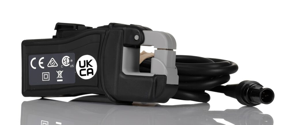
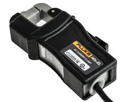
A Fluke Energy Monitor Clamp is a clamp style current sensor designed to measure electrical current without disconnecting cables or breaking a circuit. Because it clips around a conductor, it supports faster energy checks, cleaner installations, and safer troubleshooting in industrial and commercial panels. If you are tracking consumption, validating loads, or improving power management, this clamp based approach can give you dependable current data with minimal downtime.
In addition, a properly chosen clamp sensor helps you capture stable readings for trending, audits, and maintenance decisions. That matters when you are working with contactors, switches, fuses, and critical electronics where interruptions are costly and mistakes can be dangerous.
What is a Fluke Energy Monitor Clamp and how does it work?
A clamp sensor detects the magnetic field produced by current flowing through a single conductor. The clamp converts that field into a proportional signal, typically in mA or V output, or in a digital form depending on the system. Many setups use a current transformer style clamp that steps current down to a safe measurement level for an energy monitor.
Because the measurement is indirect, you do not need to cut insulation, loosen connectors, or remove terminal covers more than necessary. As a result, you can reduce exposure and still capture useful current values for analysis.
Clamp sensor vs direct measurement with test leads
Direct measurement often requires breaking the circuit or inserting a meter in series. That can be slow and increases risk in tight panels. A clamp method is usually faster because you can measure around cables while leaving the circuit intact.
However, clamp readings depend on correct placement and proper sensor selection. If the clamp is oversized, misaligned, or placed around multiple conductors, results can be inaccurate.
Why use a Fluke Energy Monitor Clamp for energy monitoring?
Energy monitoring is not only about a single reading. It is about identifying patterns, peaks, and waste over time. A clamp based current sensor helps you build that story.
Use cases include:
- Verifying load current before adding new equipment
- Tracking HVAC or motor energy behavior during shifts
- Finding unexpected standby draw on control cabinets
- Supporting energy audits and compliance reporting
- Confirming whether a circuit is operating within design limits
When you combine current data with voltage and power factor from an energy monitor, you can estimate real power and consumption more reliably.
Where clamp monitoring adds the most value
A clamp solution is especially helpful when:
- Panels are crowded and disconnecting cables is risky
- Downtime is limited and checks must be quick
- You need repeatable readings across multiple feeders
- Systems include frequent switching via contactors and relays
How to choose the right clamp for your application
Selection is where most performance problems start. The right clamp improves accuracy, stability, and safety.
Key factors to consider:
- Current range: Match expected load and allow headroom for inrush
- Conductor size: Ensure the jaw opening fits the cables you will measure
- Output type: Confirm the monitor input expects the clamp signal format
- Accuracy class: Choose the level required for billing grade or maintenance
- Environment: Heat, dust, oils, and vibration affect long term reliability
Also consider whether you need flexible coils for large busbars or a solid core clamp for standard conductors. In many installations, a solid clamp is easier to position consistently.
CT clamps and real world accuracy
Current transformer clamps can be accurate and stable, but installation details matter. Tight closure, clean contact surfaces, and correct orientation reduce phase and scaling errors. If your panel includes high frequency electronics like variable speed drives, check whether the clamp and monitor handle harmonics properly.
Installation tips for safer, cleaner measurements
Before installation, follow local electrical safety rules and site procedures. Even if a clamp avoids opening the circuit, you are still working near energized components.
Practical setup tips:
- Identify the correct conductor and clamp only one phase or one neutral as required
- Keep the clamp away from strong external magnetic sources when possible
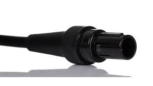
- Route sensor cables neatly to avoid pinching and strain at connectors
- Maintain separation from high heat zones and sharp edges
If you are mounting in a cabinet, plan cable routing so the clamp lead does not interfere with panel doors, switches, or moving hardware. Secure wiring with appropriate ties and keep bends gentle for long life.
Orientation and placement best practices
Many clamps have a direction indicator. Align it consistently so the monitor interprets the signal correctly. For three phase measurements, keep each clamp positioned similarly across phases to improve comparability.
Avoid these common mistakes:
- Clamping around multiple conductors, which cancels fields and shows near zero
- Leaving the jaw slightly open due to debris or misalignment
- Running clamp leads parallel to high power conductors without separation
- Placing clamps too close to contactors that generate switching noise
How to interpret readings for actionable insights
Once your Fluke Energy Monitor Clamp is capturing current, your next goal is turning readings into decisions. Current trends can reveal mechanical wear, process changes, and electrical faults.
Look for patterns such as:
- Rising current over weeks, which can indicate bearing friction or overload
- Sharp spikes, which may relate to switching events or starting conditions
- Imbalance between phases, suggesting uneven loads or wiring issues
- Unexpected nighttime current, pointing to waste or controls left active
Pairing current data with temperature and sensors
Current alone is powerful, but you can improve diagnosis by pairing it with thermal observations and other sensors. For example, elevated current plus hot connectors can indicate poor termination. Thermal checks can also reveal overheating fuses, contactors, and cable insulation stress.
If your system uses controllers, microcontrollers, or PLC inputs, the clamp data can be integrated into dashboards for alarms and optimization. In some cases, technicians export logs to laptops for analysis, then correlate events with production cycles.
Reducing noise and improving measurement stability
Modern panels often include electronics like drives, power supplies, and switching devices. That can introduce electrical noise that affects readings.
Ways to improve stability:
- Keep sensor leads away from noisy switching sections when routing cables
- Use proper grounding and follow monitor wiring guidance
- Ensure connectors are seated and strain relieved
- Inspect for worn insulation, loose terminals, and heat damaged parts
In cabinets with dense electronics, small improvements in wiring discipline can make monitoring far more reliable. Consider panel organization aids such as labeled connectors and clean cable paths.
Supporting components that matter in real installations
During maintenance and upgrades, you may encounter components that influence measurement quality or system reliability:
- LEDs and indicator circuits that reveal switching states
- Capacitor banks that change reactive behavior
- Thermal pads used for heat transfer in power electronics
- Protective fuses and disconnect switches that affect circuit continuity
- Contactors that create transient events during load switching
Keeping these elements in mind helps you interpret clamp trends accurately and avoid false conclusions.
Maintenance and long term reliability considerations
A clamp sensor is a measurement device, so it benefits from periodic checks. Dust buildup, vibration, and oils can reduce mechanical closure quality over time. Additionally, cabinet heat cycles can loosen routing and strain points.
Simple upkeep steps:
- Visually inspect clamp closure surfaces and clean gently if needed
- Confirm leads are not pinched and connectors remain secure
- Recheck scaling settings after any controller or monitor changes
- Validate readings against a known load periodically
If you use clamp data for formal reporting, document calibration intervals and installation details. Consistent practices make results more defensible and easier to replicate across sites.
Summary: Why this clamp approach fits product focused energy monitoring
A Fluke Energy Monitor Clamp supports fast, non intrusive current measurement that suits real world panels full of cables, connectors, and protective devices. When selected correctly and installed with good routing and safety habits, it can deliver dependable current data for monitoring, audits, troubleshooting, and efficiency improvements. Pair the clamp readings with thermal checks and controller based logging, and you gain a clearer view of load behavior that helps reduce risk, cut waste, and keep systems running smoothly.